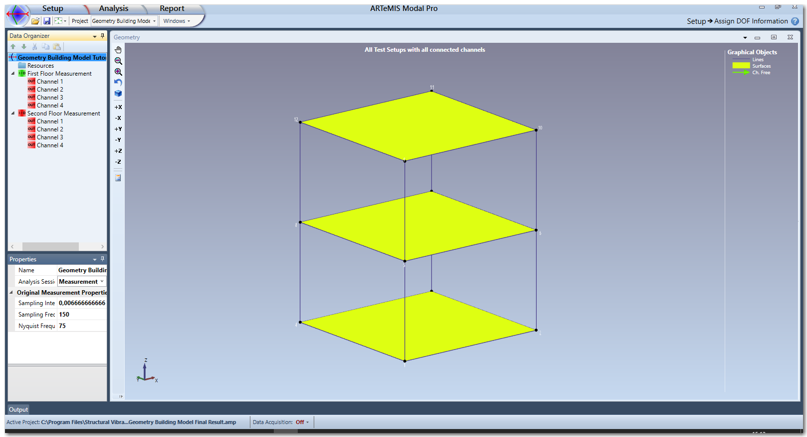
In the tutorial of the Manage Measurements Task two Test Setups were defined and measurements where uploaded. In the Assign DOF Information Task the idea is to "mount" the uploaded channel on the Geometry in the right nodal points and in the right direction. When the task is started in case of the Building Model example it looks like below:
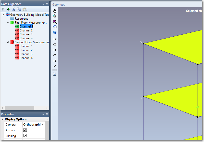
We start by clicking the Geometry window to activate the Properties window with its settings. Then we activate viewing of the Node Numbers.
Assign DOF's by Drag and Drop
To assign where a Channel Item is located on the Geometry, simply click the Channel Item in the Data Organizer and drag it out to the Nodal Point on the Geometry:
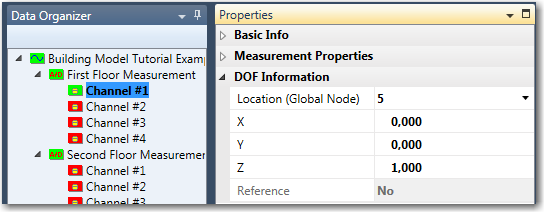
If the channel direction is not vertical you can change it to one of the principal directions +X, -X, +Y, -Y, +Z, -Z in the toolbar of the Geometry window. You can also specify both Nodal Point and Direction in the Properties window, when the Channel Item is selected in the Data Organizer:
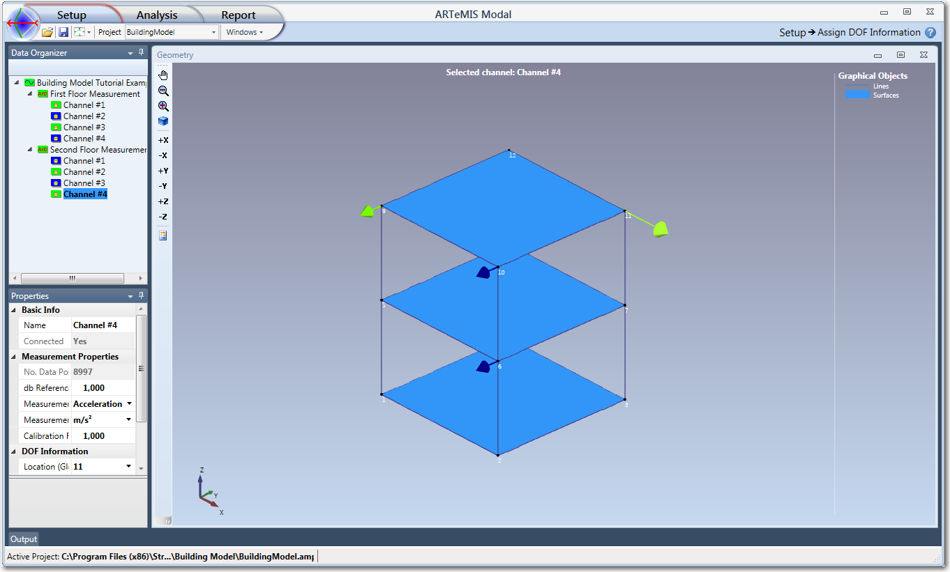
In this case we choose -Y as the direction for the first channel. After this we proceed with the remaining channels of both Test Setups. It is worth nothing that when the reference channels are positioned correctly for the second Test Setup, the color of the arrow and the tree item will automatically change to blue to indicate the channel item contains a reference sensor.
Once all channel items are mounted, and Test Setups are connected with same sampling interval for all, then you are ready to proceed to the Analysis tasks of the software. You can always go back and modify whatever is needed.
Channels from other Test Setups
As of version 3.0, the Ghost Channels are introduced i.e. preview of the connected channels from the other Test Setups. This options can be Enabled/Disabled from the Geometry Window Properties.
This options makes it much easier to connect the remaining channels to the free nodes, because the user has a clear preview of the already connected channels. The Coloring of the "Ghost" channels can be customized by the user from the Preferences, in the Geometry, Colors section.
The "Ghost" channels are not interactive i.e. hovering the mouse over them does not have any effect on the selected channels. They are just for visualization purposes of nodes already associated with channels.

See Also